///
This is a Michelson Interferometer.
Commonly used in measuring vibrations and fluctuations on a nanometer scale.
////
SETUP
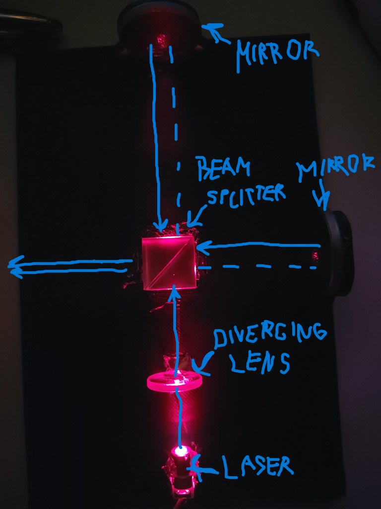
Here is the setup for this Interferometer.
Mirrors were placed on each side the light is split.
Recombined light was directed on the left side.
Diverging lens before the laser to smoothened out the light.
/////
COMPONENTS
Red Laser Diode 650nm
Lasers are desirable for It’s coherence and focus.
Standard cheap laser diode, wavelengths is 650nm giving It color red.
It’s power output was 5mW.
First Surface Mirror
Special mirrors, also used in HDD.
Standard mirrors, usually have a layer of glass or other materials that make reflect a portion of light back into itself, because of internal reflection.
First Surface Mirrors (front surface mirrors) have a direct coating surface, avoiding problems like internal reflection, ghosting and image distortions etc., therefore are used in most high precision optic instruments.
Beam Splitter
In this project cube 50/50 beam splitter was used.
Beam splitter, divides beams into two separate beams, the light is partially reflected and partially let trough, the amount of reflective coating dictates the level of reflectiveness.
The cube is the place where light splits and is reunited into a spot.
Diverging Lens (Negative Meniscus)
Due to high noise environment and low precision build, the laser beam was diverged therefore making aligning the beams more easy to establish coherence.
Negative Meniscus showed optimal results, based on the resources available.
| Components | No. of |
|---|---|
| Laser diode 650nm (red) | 1 |
| First Surface Mirror | 2 |
| Beam Splitter | 1 |
| Diverging Lens (Negative Meniscus) | 1 |
| PLA printed stand | 1 |
//////
DESIGN
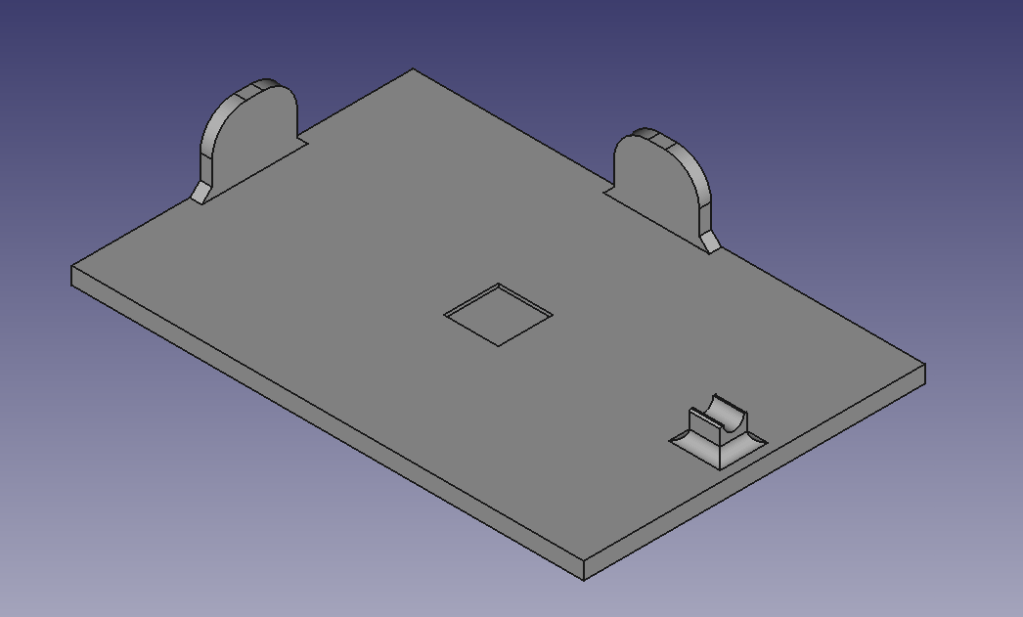
The 1st design.
First hands on experience.
This is where the first problem arose.
When a beam splitter, splits a photon into a superposition, the superposition is reflected at both mirrors, and they are re-united again at the beam splitter, causing interference.
In the 3D model is seen that Mirror 2 is further away from a beam splitter than Mirror 1, therefore the interference didn’t occur.
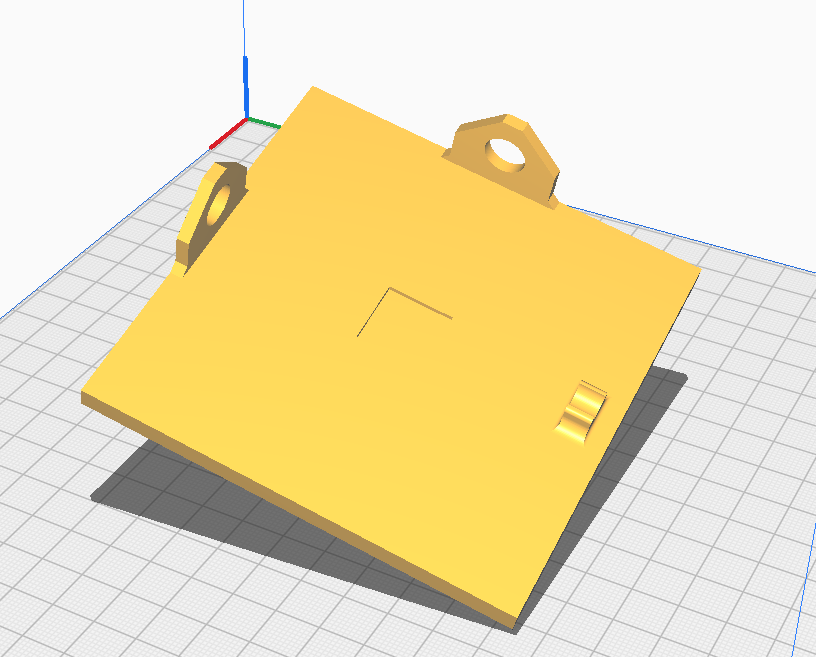
2nd design.
The holes for mirrors allowed room for adjustment, the hold for the laser was edited to make more space.
///////
RESULT
The beam splitter was glued on padded square part in the middle, the mirror had to be aligned in a way that the laser is reflected in both mirrors.
Each mirror has to be fixed on the each side after the laser was calibrated, aligning the mirrors was the part that took the longest time.
Diverging lens was put after the laser as a first contact, It slightly diverged the beam making it more optimal for interference.
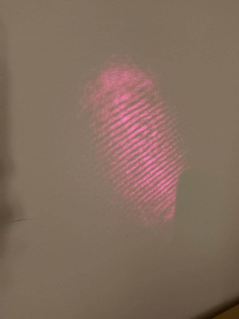
The result.
This is the interference pattern that is made out of photons that were split in two than, when recombing they sustained a certain phase shift due to environmental noise and vibration, making one portion dislocated.
When the photons recombined, they constructively and destructively interfered.
Making a pattern seen on the wall.
The degree of the environmental noise is the degree of the phase shift.
The actual vibrational distances can be measured by taking the wavelength of the laser which is 650nm.
Full rotation is 360° = 650 nm.
Let’s say I measure a 180° of a phase shift.
Meaning 360° / 2 = 180°.
Therefore 650nm / 2 = 325nm.
Equation
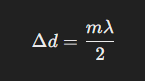

That means that by measuring the brightness of the interference, I just measured that mirror has been dislocated by 325nm.
For reference 10 000 000 nm is 1 cm.
////////
